Warmaul Assembly Instructions

Before proceeding:
You need to make sure your internal frame has been completed. Do that first if you have not yet done so.

LAAA Large Internal Frame
TOOLS NEEDED:


-
Hobby Clippers (for cleaning and removing support bits)
-
No glue necessary
PARTS NEEDED IN THESE STEPS:


-
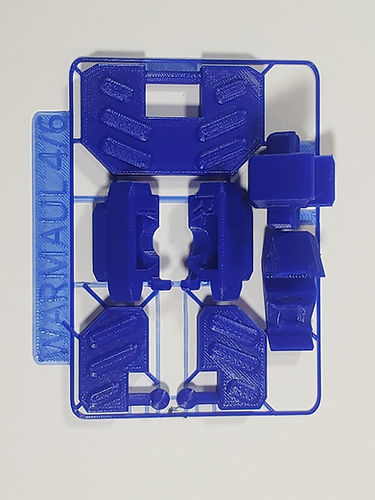
The parts used for this mech are the colored and gray parts from your kit.

-
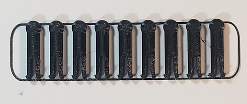
These instructions also use these black pins, which should be included in your kit.
Table of Contents
Click on any of the following links to skip ahead to that step
STEP 1: Waist


-
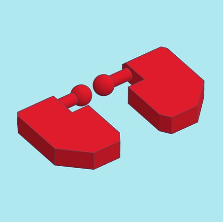
To start off, find the right side waist piece. It should have an R engraved on the inside. Be sure to remove the support bits as shown.


-
In order to attach the right side waist piece we will need to move right leg backwards at the hip. Rotate the right hip joint all the way back as shown.


-
Attach right side waist piece to right clip on the large frame's waist.

-
Using the same method as above, attach the left side waist piece.


-
Be sure to remove the support bits from the rear waist guard as shown.


-
When attaching the rear waist piece onto the rear waist clip, the rear waist guard needs to be held in place loosely so it can hang.


-
Be sure to remove the support bits from the front waist guards as shown.


-
Be sure to remove the support bits from the waist front as shown.


-
Similar to before, when attaching the front waist piece on the front waist clip, the front waist guards both need to be held in place loosely so they can hang.
STEP 2: Legs

-
Locate the two right side upper leg pieces. They should have the R engraved inside.


-
To make it easier, lift up the rear waist guard then clip on the rear right upper leg piece.


-
To make it easier, lift up the front waist guard then clip on the front right upper leg piece.


-
Clip on the left side upper leg pieces. Make sure your Warmaul matches the pictures so far. The waist guards should be able to hang by gravity without falling out. If they are falling out, reattach the waist piece and make sure the guards are seated properly.


-
Be sure to remove the support bits from the lower leg pieces as shown. These pieces don't matter which leg they attach to.


-
Clip on the front leg piece to the lower leg's front.


-
Clip on the rear leg piece to the lower leg's rear.

-
Clip on the other side's leg pieces.
STEP 3: Feet


-
Be sure to remove the support bits from all the feet parts.


-
Clip on the feet front. It does not matter which foot it is attached to.


-
Clip on the feet rear pieces.

-
Make sure both sides are clipped on.
STEP 4: Torso
Note: This kit includes alternate parts for the torso. Those instructions for the alternate parts will be included here.


-
Be sure remove the support bits from the main torso sides.

-
We will start with the right main torso side. It will be engraved with an R.


-
Attach one of the small square weapon bits by inserting it from the rear.

-
Alternatively you can use other small square weapon bits in this torso piece. Other kits have similar weapon bits that are useable here.


-
To clip on the assembled main right side you need to lift up the arm, and get the top opening of the torso piece onto the frame's shoulder as shown. Insert it from behind. Once it is on, rotate it down then clip it onto the frame's side clip.

-
As above, assemble and clip on the left main torso side piece.


-
Be sure to remove the support bits from the main torso rear as shown.


-
Be sure to remove the support bits from the main torso rear accessory as shown.


-
Clip in the accessory bit to the main torso rear.


-
Clip on the main torso rear to the rear of the internal frame.


-
Clip on the main torso front to front of the internal frame. This completes the main torso.


-
For the alternate torso parts start by removing the support bits from the alternate torso front.

-
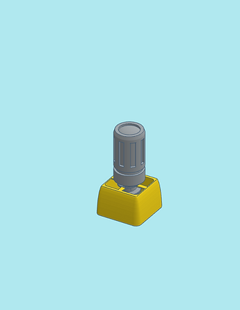
Remove the laser screw bit from its support cage by giving it a twist in either direction and pulling it out.


-
Screw in the laser bit into the alternate torso front.


-
The alternate torso front can be clipped on instead of the main torso front. Now remove the main torso rear and sides and proceed.


-
For the alternate torso sides be sure to remove the support bits from both sides as shown.


-
Small square weapon bits can fit into the alternate torso as shown.


-
Similar to how it's done with the main torso sides, clip on the right side alternate torso (engraved with an R).

-
Clip on the other alternate torso side as well.


-
Be sure to remove the support bits from the alternate torso rear as shown.


-
Clip on the alternate torso rear.
STEP 5: Arms and Arm Guns
Note: This kit includes alternate parts for the arms guns. Those instructions for the alternate parts will be included here.


-
Be sure to remove the support bits from the upper arm parts as shown.

-
Start by gathering the right side upper arm parts, engraved with an R on the inside.


-
Clip on the upper arm front to the right side of the frame.


-
Clip on the upper arm rear to the right side of the frame.

-
Similarly, clip on the upper arm parts to the left side.


-
Be sure to remove the support bits from the lower arm shroud as shown.


-
The lower arm shroud can be slipped on to the frame's lower arm at an angle as shown.

-
Slide on the other side's lower arm shroud.


-
Insert a pin into each arm gun as shown.


-
Clip in the assembled arm gun into the lower arm. It should go through the arm shroud and into the internal frame's clip.

-
You can use the alternate gun bits on either arm.

-
Do the same for the other side.
STEP 6: Side Torso Bits
Note: This kit includes alternate parts for the side torso bits. Those instructions for the alternate parts will be included here.


-
Be sure to remove the support bits from the short missile pod as shown.


-
Insert one of the side torso pins into the short missile pod in the orientation as shown.


-
Clip in the short missile pod into the top right side of the torso frame.
-
For the long missile pod, be sure to remove the support bits as shown.


-
The long missile pod has a protective door which can be closed or opened when desired.

-
Clip in one of the side torso pins in the orientation as shown.

-
Clip the long missile pod into the top right side of the torso frame.


-
For the left side parts start by removing the support bits from the large sensor pod as shown.


-
Insert one of the side torso pins into the large sensor pod in the orientation as shown.

-
This large sensor pod fits on the left side of the torso frame.


-
For the small sensor pod, be sure to remove the support bits and insert a side torso pin into it in the orientation as shown.
-
Your Warmaul is now complete! Feel free to mix and match parts that will fit, even with parts from other kits. A lot of parts in our Mechbay kits were designed for cross-kit modularity.


-
If you have not yet done so, proceed to assembling your bonus General Issue Power Armor (GIPA) mini that comes in your kit!

General Issue Power Armor