Large Internal Frame Assembly Instructions
(type: LAAA)

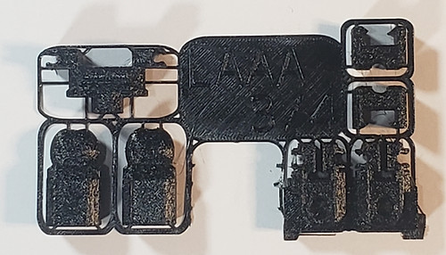
These instructions are for the large internal frame that comes with the Warmaul and Skullface Mechbay Wave #1 kits. This frame needs to be assembled before proceeding to the weapon and armor parts of your mech.
TOOLS NEEDED:


-
Hobby Clippers (for cleaning and removing support bits)
-
No glue necessary
PARTS NEEDED IN THESE STEPS:


-
The parts used in this frame are all from the black parts in your kit.
Table of Contents
Click on any of the following links to skip ahead to that step
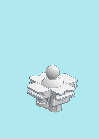
STEP 1: Waist


-
Be sure to remove the support bits from the waist part as shown.

-
Clip the two waist parts together as shown. The upper ball joint part snaps onto the cross waist.


-
Be sure to remove the support bits from all the ball joints as shown. We will use two of them for the hip ball joints.


-
Insert the hip ball joints into the bottom of the assembled waist.

-
Clip in the hip joint cap into the bottom of the assembled waist, making sure the hip ball joints fit into the holes of the hip joint cap. The hip ball joints should be able to pivot in the waist.
STEP 2: Legs


-
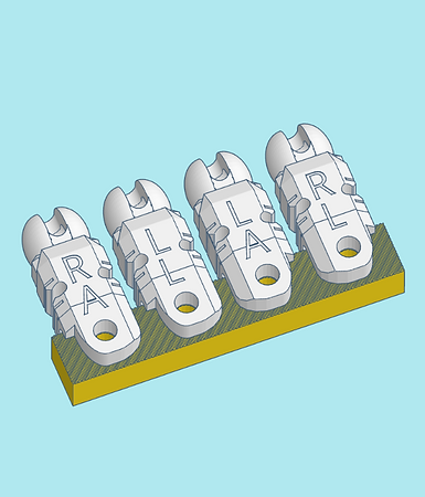
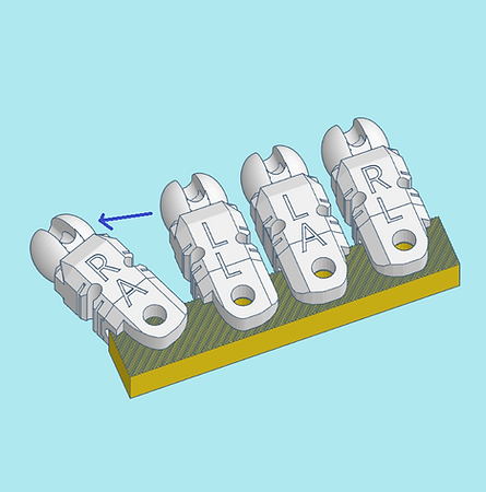
The upper leg and upper arm parts need to be removed from their support scaffold. You will need to tightly grip the support scaffold and rip the leg and arm parts free. It may take a lot of force, but they should all tear free.


-
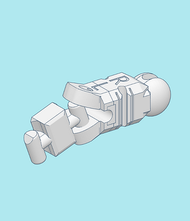
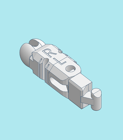
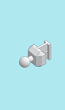
We will start with the part labeled R L (Right Leg). To make sure it is oriented correctly, take a knee joint and insert it into the hole on the leg part as shown. This is to make sure when you insert it properly that the knee will bend in the correct direction.

-
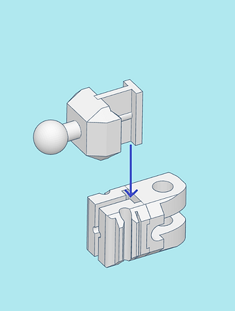
You will need to insert the knee joint into the upper leg by spreading it open slightly, and inserting one of the knee pegs into the holes.

-
You should then be able to shove the other peg into the other hole.

-
Inspect your assembled piece to make sure it matches the picture shown. This is to ensure the knee bends properly.


-
Similar to before, the upper parts of the lower legs need to be torn free from their support scaffolds. Again, force will need to be applied to tear them free.

-
Be sure to remove the support bits from the lower leg's ball joints as shown.

-
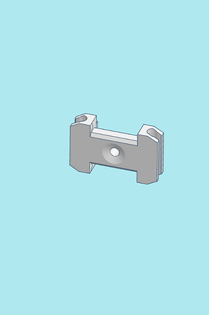
Clip the two lower leg parts together. The orientation of the ball joint part does not matter.


-
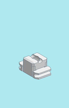
Using the same method above, connect the lower leg to the knee joint, making sure all parts are oriented correctly as shown. Otherwise the knee will not bend properly


-
Attach the leg to the right hip ball joint.

-
Assemble and attack the left leg using the instructions above

-
Check to make sure your legs are both assembled correctly.
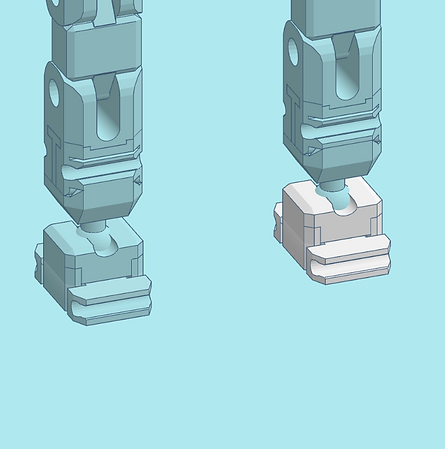
STEP 3: Feet


-
Be sure to remove the support bits from the feet part as shown.


-
Clip the two feet parts together shown. Ensure the bottom part is oriented to where recessed part of the hole is at the top, and the protruded I is at the bottom.


-
Clip the foot onto the lower leg ball joint. The direction it is facing does not matter.
-
Assemble and clip on the other foot.


-
Before proceeding to the next step, ensure that what you have built resembles these images.
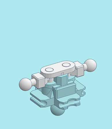
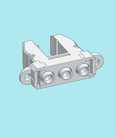
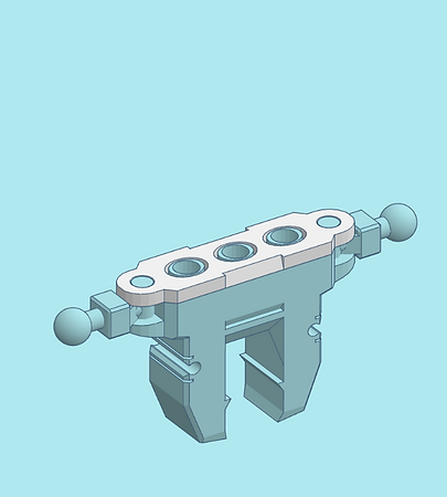
STEP 4: Torso

-
Be sure to remove the support bits from the upper torso as shown.


-
Insert the shoulder ball joints into the upper torso as shown.


-
Be sure to remove the support bits from the torso joint cap as shown.

-
Clip in the torso joint cap into the top of the assembled torso, making sure the shoulder ball joints and clips fit into the holes of the torso joint cap. The shoulder ball joints should be able to pivot in the torso.


-
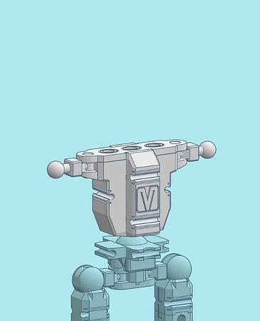
Clip on the final torso part to the assembled torso as shown. The bottom when inserted all the way should be flush with the top of the joint cap. Note the engraven M logo is considered the front of the mech's frame.

-
Clip on the assembled torso to the waist
STEP 5: Arms

-
Locate one of the upper arm pieces engraved with an R A (Right Arm). Insert an elbow ball joint similar to the method shown in step 2.


-
Clip on the assembled right arm onto the right side of the torso.

-
Using the instructions above, assemble the left upper arm and clip it onto the left side of the torso.


-
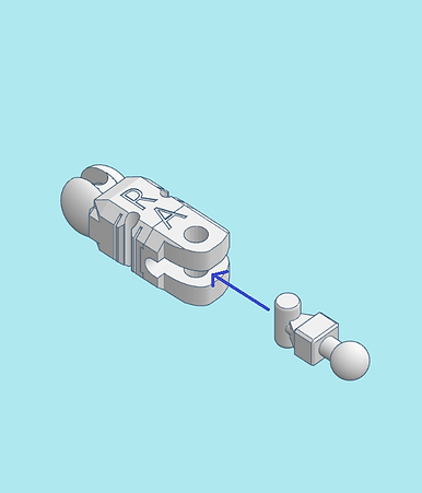
Clip on a lower arm to the upper arm. Note the orientation of the lower arm as shown by the blue lines.

-
Clip on the other lower arm to the other side.


-
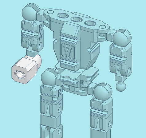
Your large frame should now be assembled. Please refer to the pictures to make sure yours is assembled properly, noting angles and directions the joints, knees, and elbows face.
-
Proceed to instructions on assembling your mech. The following kits use this large frame:

Warmaul

Skullface