Skullface Assembly Instructions

Before proceeding:
You need to make sure your internal frame has been completed. Do that first if you have not yet done so.

LAAA Large Internal Frame
TOOLS NEEDED:


-
Hobby Clippers (for cleaning and removing support bits)
-
No glue necessary
PARTS NEEDED IN THESE STEPS:


-
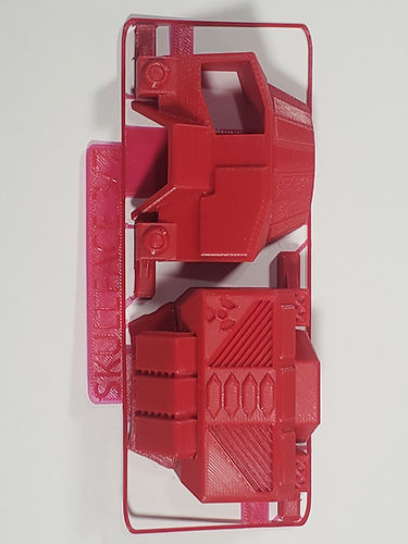
The parts used for this mech are the colored and gray parts from your kit.

-
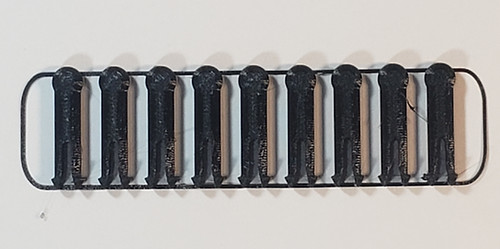
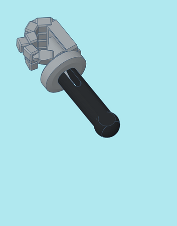
These instructions also use these black pins, which should be included in your kit.
Table of Contents
Click on any of the following links to skip ahead to that step
STEP 1: Waist


-
Be sure to remove the support bits from the rear waist as shown.


-
Clip on the rear waist to the internal frame.


-
Be sure to remove the support bits from the waist front as shown.


-
Clip on the waist front to the internal frame.
STEP 2: Legs


-
Be sure to remove the support bits from the upper leg parts as shown.

-
Locate the two right side upper leg parts. They are engraved with an R as shown.


-
Clip on the upper leg front to the internal frame's right leg.


-
Clip on the upper leg rear to the internal frame's right leg.

-
Similarly clip on the left leg parts.


-
Be sure to remove the support bits from the lower leg parts as shown.


-
Clip on the lower leg front to the internal frame's lower leg. The side does not matter.


-
Clip on the lower leg rear to the internal frame's lower leg.

-
Clip on the other leg's pieces.
STEP 3: Feet


-
Be sure to remove the support bits from the feet parts as shown.


-
Clip on rear foot part to internal frame. The side it is clipped on does not matter.


-
Clip on the front foot part to the internal frame.

-
Clip on the other side's foot pieces.
STEP 4: Torso
Note: This kit includes alternate parts for the torso. Those instructions for the alternate parts will be included here.


-
Be sure to remove the support bits from main torso rear as shown.


-
Clip on the main torso rear to the internal frame.


-
Be sure to remove the support bits from the main torso front as shown.


-
The main front torso's weapon bit has to be inserted from the back.

-
The kit comes with an alternate torso weapon bit that can take screw bits from this and other Mechbay kits.


-
Clip on the main torso front to the internal frame.


-
For the alternate torso, be sure to remove the support bits as shown.


-
Clip on the front and rear parts of the alternate torso. You can have a mixed combination of main and alternate torso parts.
STEP 5: Torso Weapon Pods
Note: This kit includes alternate parts for the torso weapon pods. Those instructions from the alternate parts will be included here.


-
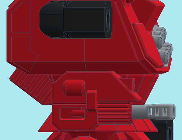
Be sure to remove the support bit from the main right side torso weapon pod as shown.


-
Remove the autocannon screw bit from its support cage by giving it a twist in either direction and pulling it out.


-
Screw in the autocannon bit unto the main right side torso weapon pod.


-
Attach the weapon pod into the right side of the torso by first opening it up slightly (pulling the 2 torso halves apart) then inserting the ball joint into the hole.


-
Once the weapon pod is in, close up the gap to hold the weapon pod in place.


-
For the alternate right side torso weapon pod be sure to remove the support bit as shown.

-
Remove the railgun screw bit from its support cage by giving it a twist in either direction and pulling it out.


-
Screw in the railgun bit unto the alternate right side torso weapon pod. The screw hole (as well as the one from the main weapon pod) is compatible with other screw-in bits from this and other Mechbay kits.

-
Using the same method as above, attach the alternate right side torso weapon pod to the mech.


-
For the left side missile weapon pod be sure to remove the support bit as shown.

-
This pod attaches to the left side of torso in the same manner as the right side pods.


-
For the left side blank pod be sure to remove the support bit as shown.

-
The blank pod attaches to the left side of the torso.
STEP 6: Head
Note: This kit includes alternate parts for the head. Those instructions for the alternate parts will be included here.


-
Be sure to remove the support bit from the main head as shown.


-
Insert a pin into the main head as shown.


-
Clip on the head to the torso center hole. The head should be able to move around a little when clipped in.

-
The alternate head is assembled and attaches in the same way.
STEP 7: Arms, Hands, and Shoulders
Note: This kit includes alternate parts for the hands. Those instructions for the alternate parts will be included here.


-
Be sure to remove the support bits from the upper arm parts as shown.

-
Gather the right side upper arm parts. They are engraved with the R on the inside.


-
Clip on the front side of the upper arm to the internal frame.


-
Clip on the rear side of the upper arm to the internal frame.

-
Clip on the left arm parts to the left side of the internal frame.


-
Be sure to remove the support bits from the lower arm shrouds as shown.


-
Slide on the lower arm shroud onto one of the lower arms of the internal frame as shown.

-
Do the same on the other side.


-
Be sure to remove the support bits from the empty hands as shown.

-
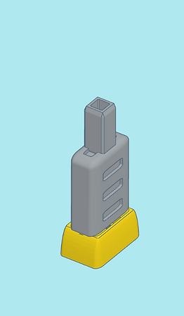
Insert a pin into each hand bit as shown.


-
Clip on the assembled hands to the lower arms. They should go through the arm shrouds and into the inter frame's clips.


-
Be sure to remove the support bits from the laser hands as shown, and insert pins and clip them onto the lower arms.


-
The gatling autocannon needs to have its support bits removed as shown.


-
Insert the rotating pin into the gatling autocannon.


-
Clip on the barrel assembly to the rotating pin. The barrels should be able to spin once attached.

-
Insert a black pin into the gatling autocannon and clip it onto the right lower arm.

-
Mix and match the left and right hands on your Skullface.


-
Be sure to remove the support bits from the shoulder guards as shown.


-
Snap on the shoulder guards to the housing near the top of the torsos as shown.
-
Your Skullface is now complete! Feel free to mix and match parts that will fit, even with parts from other kits. A lot of parts in our Mechbay kits were designed for cross-kit modularity.


-
If you have not yet done so, proceed to assembling your bonus General Issue Power Armor (GIPA) mini that comes in your kit!

General Issue Power Armor