Notre Dame Assembly Instructions

Before proceeding:
You need to make sure your internal frame has been completed. Do that first if you have not yet done so.

MAAA Medium Internal Frame
TOOLS NEEDED:


-
Hobby Clippers (for cleaning and removing support bits)
-
No glue necessary
PARTS NEEDED IN THESE STEPS:


-
The parts used for this mech are the colored and gray parts from your kit.


-
These instructions also use these black pins, which should be included in your kit.
Table of Contents
Click on any of the following links to skip ahead to that step
STEP 1: Waist


-
Be sure to remove support bits from the waist rear as shown.


-
Clip on to rear of internal frame waist.


-
Be sure to remove support bits from the waist front as shown.
-
Clip on to front of internal frame waist.


STEP 2: Legs


-
Be sure to remove support bits from the upper leg parts as shown.


-
Clip on the front of the upper leg as shown on the internal frame. The side does not matter.


-
Clip on the back of the upper leg as shown.

-
Similar to above, clip on the left side parts.


-
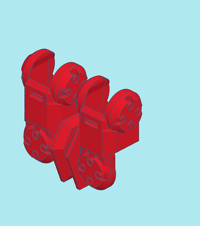
Be sure to remove the support bits from the lower legs as shown.

-
Gather the lower leg parts with the R engraved on the inside as shown.


-
Clip on the outside part of the right lower leg.


-
Clip on the inside part of the right lower leg.

-
Similar to above, clip on the left side parts.
STEP 3: Feet


-
Clip on the front foot part as shown. Which side does not matter.


-
Clip on the rear front foot part as shown.
-
As above, clip on the other side foot parts.

STEP 4: Torso
Note: This kit includes alternate parts for the torso. Those instructions for the alternate parts will be included here.


-
Be sure to remove the support bits from the rear part of the main torso as shown.


-
Clip the main torso rear onto the rear of the internal frame.


-
Be sure to remove the support bits from the front of the main torso as shown.


-
Clip the main front torso to the internal frame's torso front.


-
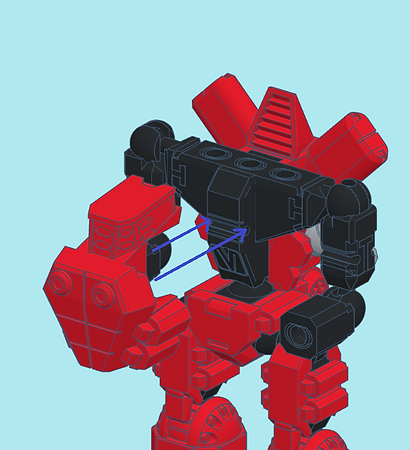
For the alternate torso first start by making sure to remove the support bits from the rear of the alternate torso as shown.


-
Be sure to remove the support bits from the thrusters as shown.


-
Clip on the thrusters to the alternate rear torso. The thrusters should be able to rotate on the torso rear once clipped on.


-
Clip on the assembled alternate rear thruster to the frame.


-
Be sure to remove the support bits from the alternate torso front as shown.

-
Clip on the alternate torso front to the frame.


-
You can mix and match main and alternate parts for the torso.
STEP 5: Shoulders
Note: This kit includes alternate parts for the shoulders. Those instructions for the alternate parts will be included here.


-
Be sure to remove the support bits from the main right shoulder as shown.


-
Insert one of the black pins into the main right shoulder as shown.


-
Clip the main right shoulder into the right hole at the top of the torso.


-
Insert one of the black pins into the main left shoulder as shown.


-
Clip the main left shoulder into the left hole at the top of the torso.


-
For the alternate shoulders, be sure to remove the support bits from both alternate shoulders as shown.


-
Insert a black pin into each of the alternate shoulders as shown.

-
Clip the alternate shoulder into the left and right holes at the top of the torso.


-
You can mix and match the shoulders with the torso parts.


-
The main left shoulder can receive one of the screw bits from your kit. Twist and remove one of the screw bits from its support cage. This is the method to remove all the screw parts that are used in the rest of the kit.


-
Screw in the laser bit into the left main shoulder as shown.


-
The main right shoulder can received weapon bits. The larger space requires the use of the adapter for the smaller square bits. Insert a small square bit into the adapter from the back, and fit the adapter into the shoulder. It may be difficult to insert or remove the bits at first, but each subsequent inserting and removal gets easier.


-
These smaller square bits are using the adapter.

-
This laser array can only fit in the large space without the adapter.


-
These smaller square bits can fit in the alternate shoulder without an adapter. Experiment with swapping bits from other kits. Mechbay kits are designed for some cross kit compatibility.
STEP 6: Arms and Hands
Note: This kit includes alternate parts for the arms and hands. Those instructions for the alternate parts will be included here.


-
Be sure to remove the support bits from the upper arm parts as shown.

-
Locate the upper arm parts shown. We will start with the ones engraved with an R on the inside.


-
Clip on the front upper arm part to the front of the right side of the internal frame.


-
Clip on the rear upper arm part to the rear of the right side of the internal frame.

-
Similar to above, clip on the parts to the left side.


-
Screw weapon bits into both arm shrouds.


-
Slide on the lower arm shroud onto one of the lower arms of the internal frame as shown.

-
Slide on the other lower arm shroud onto the other lower arm.


-
Be sure to remove the support bits from the alternate shielded lower arm as shown.

-
The alternate shielded arm shroud is designed to fit on the left lower arm.


-
Be sure to remove the support bits from the open hands as shown.


-
Insert a black pin into each of the open fist and closed fist hand bits.


-
Clip in the hand bits into the lower arms. They should go through the arm shrouds and into the internal frame's clips.
-
Your Notre Dame is now complete! Feel free to mix and match parts that will fit, even with parts from other kits. A lot of parts in our Mechbay kits were designed for cross-kit modularity.


-
If you have not yet done so, proceed to assembling your bonus General Issue Power Armor (GIPA) mini that comes in your kit!

General Issue Power Armor